


GEN PRO-LB-EU 12K – UK whole-house EPS
Published: 2026-09-30 16:37:28
Updated: 2026-09-30 09:37:37
The GEN PRO-LB-EU 12K supports G99 with Rule 5, integrated anti-islanding and an internal N-PE bond. Whole-house EPS still needs an external ATS.

GEN PRO-LB-EU 12K – UK whole-house EPS
How does the gen pro-lb-eu 12k support g99 work, typical output, costs and limits, and whether they have a future for UK homes, balconies and businesses.
Does the GEN PRO-LB-EU 12K support G99?
Yes. On the specification covered here, the GEN PRO-LB-EU 12K supports G99. Rule 5 is selectable, so Great Britain protection parameters can be applied. Integrated anti-islanding is included. No extra Loss of Mains relay is specified for the standard configuration. Transfer to EPS, the emergency power supply output, is stated to open both live and neutral and to apply an internal neutral-earth bond. Whole-house backup still needs an external automatic transfer switch, because the grid port does not feed the house off-grid. A menu choice is not distribution network operator consent.
The same description gives the inverter separate GRID and EPS/LOAD connections, up to 100 A continuous AC passthrough, and a 12 kW UPS output. Confirm those figures on the datasheet and nameplate for the exact variant before they are used in a design. They describe different jobs. Passthrough is not backup power. A 12 kW UPS figure is not permission to run every circuit in the house at once.
Match the installed unit to the cited device record. Confirm the grid code on the firmware that will actually be commissioned. Design the transfer switch and earthing with the inverter's own disconnection and bond. Only then does a G99 application describe the equipment that will be connected.
What a G99 setting does not replace
Engineering Recommendation G99 is the Great Britain recommendation used where generation operates in parallel with the distribution network and the smaller G98 route does not apply. G98 is the route generally used for fully type-tested microgeneration up to 16 A per phase. Nothing in the material used here establishes that this inverter can be connected on that smaller route. A 12 kW hybrid should not be assumed to be a G98 device.
Selecting Rule 5 applies a grid code inside the inverter. It does not submit an application, does not set an export limit, and does not prove that the firmware on the wall matches a type-test entry. The distribution network operator still has to see the capacity, the phase arrangement and any export constraint that belongs to that site. A later change of grid code can leave the tested protection settings different from the settings in use. Make the choice before tests and keep it on the commissioning record.
G99 in this context is a Great Britain recommendation. It should not be used as the connection rule for Northern Ireland. MCS certification, and any export-tariff eligibility, are also separate questions. Neither follows from a selectable grid code. Neither is established by the specification covered here.
Is an external Loss of Mains relay required?
No additional external Loss of Mains relay is specified for the standard G99 configuration. The inverter is described as having integrated anti-islanding and grid monitoring, with the relevant G99 protection parameters applied when it is operating under Rule 5. Loss of Mains protection stops the inverter from energising a network that has gone dead. It is not the same function as keeping the house supplied.
That "not specified" answer is for the standard configuration. It is not a promise that every network operator, every multi-inverter site, or every altered-settings case will accept the inverter alone. If the manufacturer's instructions for the installed firmware, or the connection offer for that site, ask for an external relay, the relay is part of the job. Fitting one "just in case", without checking how it interacts with the integrated protection, is not an improvement.
Backup still needs a home battery or other source that the inverter can actually use, an EPS output that stays within its stated rating, and a lawful way to move the load off the failed grid. Anti-islanding on its own only separates generation from the network. It does not feed the consumer unit.
What happens to live, neutral and earth on EPS
Yes. Both live and neutral are stated to open when the inverter transitions to off-grid EPS operation. An internal neutral-earth bond is also stated to be built in for that off-grid mode, so the islanded supply has a local earth reference rather than relying on the network neutral. Those two behaviours belong together. Opening live only, or bonding neutral to earth while the network neutral is still connected, would be a different and unsafe arrangement.
On a PME supply, also called TN-C-S, island-mode earthing has to be designed around that internal bond and around the live-and-neutral disconnection. The bond is not, by itself, a complete PME backup design. Whether a separate earth electrode is required is not established here. Decide that from the supply type and the manufacturer's earthing instructions, not by assumption either way. If the automatic transfer switch also switches neutral, or closes an earth link of its own, the two devices must be specified as one system. An islanded installation with two neutral-earth bonds, or with none, is not a finished design.
Earth-fault current takes a different path once the internal bond is the reference. Residual-current devices that were correct while the house was on the grid may need another look on the backed-up side. Copying the grid-connected protection schedule across without that review is a common gap. The inverter chassis looks unchanged even though the fault loop is not.
Why whole-house EPS still needs an external ATS
Yes. An external automatic transfer switch is required for the whole-house arrangement described here. In off-grid mode the GRID port will not provide output, while the EPS/LOAD port provides the backup supply. The transfer switch moves the house load from the grid supply to that EPS supply, and back again when the grid returns. The inverter does not do that whole-house changeover on the grid port.
The GRID and EPS/LOAD connections can each be connected directly to their own port on the inverter. That is what the separate terminals are for. The grid supply uses the GRID connection for normal parallel operation. The backup supply uses the EPS/LOAD connection during off-grid operation. They must not be tied together, and they must not be treated as two sources to parallel. Reject any drawing that lands both ports on the same busbar because both cables leave the same chassis.
The stated 100 A continuous AC passthrough is the grid-side current the inverter is said to carry while the grid is present. It is not 100 A of battery or solar backup. The stated backup limit is the 12 kW UPS output. Phase count is not established in the material used here, so that kilowatt figure should not be converted into an assumed backup current. The incoming cut-out fuse still caps what the grid side can carry. A passthrough claim does not raise the fuse. Circuits left on the EPS side, including any large heat pump, electric shower or EV charger, have to be chosen so their simultaneous demand can stay inside the UPS output, with allowance for motors that start above their running load. Space for the transfer switch and a clear split between backed-up and grid-only boards matters as much as the inverter rating.
What to check before citing G99 on an application
The certification lookup cited for this model is device code LUXPO/19557/V1/A2. The live page is the ENA generation device record for that code. This article does not reproduce fields from that page. Before the record is named on an application, the registered manufacturer, model, firmware and phase arrangement need to match the nameplate of the unit being installed. A type-test entry, where the live page shows one, still does not set the export limit and does not guarantee that every configuration will be accepted. Where the nameplate cannot be matched, the record should not be used as proof for that inverter. Multi-unit sites, a different firmware build, or a grid code other than the one that was type tested can all change what the network operator will accept. Export limitation, if it is required, is a site condition. It is not something Rule 5 sets by itself. Confirm the 12 kW and 100 A figures on the current datasheet before they are written into a design or a connection form. The comparison below is a decision check, not a set of measured test results.
When this is the wrong question to rely on
This is for a Great Britain household, or for the installer working on that property, checking this named inverter before a G99 application or a whole-house EPS design. The decision it supports is whether the grid code, the integrated protection and the port layout are even the right starting point. It does not price the inverter, size a battery, or estimate how long a house would run in an outage. Those figures are not established here.
It is the wrong guide for a system that never operates in parallel with a distribution network, because G99 is about that parallel connection. It is not a Northern Ireland connection guide, and it is not a wiring instruction. It is also the wrong place to treat a selectable grid code as consent, or to treat a 12 kW hybrid as eligible for the G98 route without evidence. A reader comparing retail battery prices is on a different question. Nothing here ranks this inverter against other products on cost or value.
What to agree before the equipment is ordered
The grid code is a commissioning choice, not a factory state a homeowner can assume was left correct. The installer has to confirm that Rule 5 is still the G99 label on the installed firmware, select it before protection tests, and keep a record of the setting that was tested. If the connection offer later requires a different configuration, the offer wins over the menu that happened to be selected on the bench. Commissioning should sit with a qualified electrician.
The transfer switch should be agreed before it is ordered, not after the boards are built. Neutral switching and any earth link in the switch have to be read against the inverter opening both live and neutral and making its own off-grid bond. Agree the backed-up load list in the same conversation. A whole-house label on a drawing is not the same as a house whose simultaneous load can stay within 12 kW.
Ask for that set in writing with the connection paperwork, including whether an external Loss of Mains relay has actually been required for this site. Do not order a transfer scheme that assumes an export limit or an extra relay the network operator has not set. A matched nameplate, a recorded grid code and an ATS schedule that agrees with the inverter are the checks that make the yes on G99 usable. If the rest of the design is still open, book a free survey.
Plan, Compare & Buy Renewable Energy Solutions
AI does the thinking.
You get the perfect solar match.
Use RoboMo™ to assess your property, compare available technologies and connect with trusted UK installers, suppliers and manufacturers.
Simply enter your postcode, drop a pin on your roof, create your free account and let RoboMo™ analyse your property to find the best solar panels for your home.

You don't have to think
RoboMo™'s AI analyses your roof and does all the hard work.

Accurate & tailored
AI-powered assessment based on your roof, location, and conditions.

Best options, maximum savings
Compare top solar panels for the best performance and value.

Simple, fast & effortless
Provide a few details, sit back and watch your results unfold.
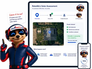
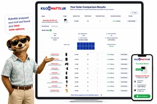
STEP 1
Choose Home, Business or Industrial
Enter your postcode to start your assessment.
STEP 2

Drop a pin on your roof
STEP 3

Create your free account
STEP 4

Sit back and watch RoboMo™ work
RoboMo™ analyses your roof and builds your personalised solar comparison.

Step 1
Enter your postcode
Start designing your wind energy system in seconds.
Are you an installer, distributor or renewable energy business?
Kilowatts UK is expanding the Flower Turbines partner network across the UK.
Become A Flower Turbines PartnerKilowatts UK is an authorised representative
Flower Turbines
Compact vertical-axis turbines built for real UK sites, not just open farmland.
They start in light wind, sit in a small footprint, and are bird-safe by design. Cluster them as a bouquet and the group performs better together than the same turbines standing alone. Enter your postcode for a location-based generation estimate. Figures use area weather data and will differ if buildings, trees or hills sit in the way.
Starts in light UK wind
Built to generate in typical UK wind, not only open farmland.
Small rooftop or ground footprint
Compact towers for roofs, yards and tight sites.
Bird-safe slow rotation
Slow vertical-axis spin, bird-safe by design.
Bouquet clusters raise output
Grouped turbines outperform the same units standing alone.
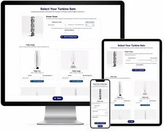
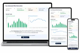
STEP 2

Choose a location
STEP 3
Place your cluster
Tap the map where you want the turbine cluster to go.
STEP 4

Instant generation forecasts
Compare different turbine layouts and see annual generation forecasts instantly.
STEP 5

No commitment required
Explore different configurations before deciding whether to request a quotation.
Related articles

FAQ
Need Help? RoboMo's Got Answers
Does the GEN PRO-LB-EU 12K support G99?
On the specification covered here, yes. Rule 5 is selectable, so Great Britain protection parameters can be applied, and integrated anti-islanding is included. Confirm the grid code on the firmware that will actually be commissioned, and match the installed unit to the cited device record before it is named on an application. A setting in the menu is not distribution network operator consent.
Does selecting Rule 5 replace a G99 application?
No. Selecting Rule 5 applies a grid code inside the inverter. It does not submit an application, set an export limit, or prove that the firmware on the wall matches a type-test entry. The distribution network operator still has to see the capacity, the phase arrangement and any export constraint for that site. A later change of grid code can leave the tested protection settings different from the settings in use.
Can this 12 kW hybrid be connected under G98?
Nothing in the material used here establishes that this inverter can be connected on the G98 route. G98 is generally used for fully type-tested microgeneration up to 16 A per phase, and a 12 kW hybrid should not be assumed to be a G98 device. G99, as discussed here, is a Great Britain recommendation and should not be treated as the connection rule for Northern Ireland. MCS certification and any export-tariff eligibility are separate questions, and neither follows from a selectable grid code.
Is an external Loss of Mains relay required?
No additional external Loss of Mains relay is specified for the standard G99 configuration. The inverter is described as having integrated anti-islanding and grid monitoring when operating under Rule 5. That is not a promise that every network operator, every multi-inverter site, or every altered-settings case will accept the inverter alone. If the manufacturer's instructions for the installed firmware, or the connection offer for that site, ask for an external relay, the relay is part of the job.
Why does whole-house EPS still need an external automatic transfer switch?
In off-grid mode the GRID port will not provide output, while the EPS/LOAD port provides the backup supply. An external automatic transfer switch moves the house load from the grid supply to that EPS supply, and back again when the grid returns. The two ports must not be tied together or treated as sources to parallel. Backup also needs a battery or other source the inverter can use, and the circuits that transfer have to stay within the stated UPS output.
Is the 100 A passthrough the same as backup power?
No. The stated 100 A continuous AC passthrough is the grid-side current the inverter is said to carry while the grid is present. It is not 100 A of battery or solar backup, and a passthrough claim does not raise the incoming cut-out fuse. The stated backup limit is the 12 kW UPS output, which is not permission to run every circuit at once. Phase count is not established here, so that kilowatt figure should not be converted into an assumed backup current. Confirm both figures on the datasheet and nameplate for the exact variant.
What happens to live, neutral and earth when the inverter transfers to EPS?
Both live and neutral are stated to open on transfer to off-grid EPS, and an internal neutral-earth bond is stated to be applied so the islanded supply has a local earth reference. On a PME supply, also called TN-C-S, island-mode earthing has to be designed around that bond and that disconnection. The bond is not, by itself, a complete PME backup design, and whether a separate earth electrode is required is not established here. If the transfer switch also switches neutral or closes an earth link, the two devices must be specified as one system so the island has one neutral-earth bond, not two or none. Residual-current devices that were correct on the grid may also need another look on the backed-up side.
What should be agreed before the equipment is ordered?
Agree the transfer switch before it is ordered, including its poles, whether it switches neutral, and whether it closes an earth link of its own. Agree the backed-up circuit list at the same time, because a whole-house label is not the same as a load that can stay within the stated 12 kW UPS output. The installer should confirm that Rule 5 is still the G99 selection on the installed firmware, select it before protection tests, and record the setting used. Before the ENA device record for code LUXPO/19557/V1/A2 is cited, the manufacturer, model, firmware and phase arrangement need to match the nameplate.